The velocity modifier applies a velocity field as a function of position.
To set a velocity field you add a velocity modifier to every sub-objects. Click on the Add button and select the Velocity modifier and then click OK to confirm the selection.
Several sub-objects may share an instanced copy of a velocity modifier in order maintain a common velocity field.
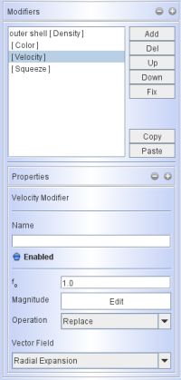
The main modifier panel for the velocity field is similar to other modifiers, providing for a name text field, a button to enable/disable and an f0 factor that is a quick way to increase the overall magnitude of the velocity field.
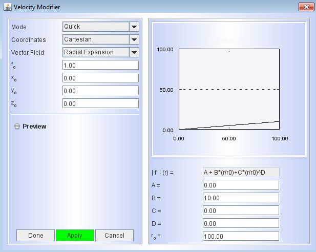
The magnitude of the velocity as a function of position is set using the graph that opens when you click on the Edit button. It is similar to other graphs, but has a few important differences, since the velocity is a vector quantity and not a scalar like density or temperature.
To ease the setup of common velocity fields, there are several presets that determine the direction of the velocity vector. They can be chosen from the Vector Field drop-down list. The presets include:
Radial Expansion, Rotation, Random, Surface Normal, and Custom |
|
Radial Expansion:
As its name suggests, all velocity vectors point radially away from the local coordinate origin. The magnitude of the velocity can be set as a function of position in the graph tool (click on the Edit button to open). The 3D function for the magnitude is separable, i.e.
v(r,θ,φ) = v1(r) * v2(θ) * v3(φ)
Rotation:
The Rotation preset makes all velocity vectors tangential to circles with their axis along the local z-axis. Again, the magnitude of the velocity can be set as a separable function of position in the graph tool. It allows you to easily set up velocity fields for accretion disks or rotating stars.
Random:
This velocity preset assigns every particle or mesh element a random velocity. In a grid based rendering, if there are more than one element in a cell, then a weighted average velocity is assigned to the cell. The weighting is by density. Possible uses for a random velocity modifier include adding a turbulent component to an otherwise systematic velocity field.
Surface Normal:
The velocity vector is perpendicular to the surface. Since the surface of each mesh element is flat, all particles on such an element have the same velocity direction. Surfaces of high curvature should therefore have sufficient segments to accurately represent the velocity field. The number of surface segments can be changed in the Primitive parameter panel. Note, that the Surface Normal velocity field should only be applied to meshes with the Distribution parameter in Surface mode.
Custom:
In the Custom mode, each velocity component is defined as a function of position in its appropriate coordinate system. Here each component i is defined as, e.g., (not fully implemented yet)
v_i (r,θ,φ) = v1_i (j) * v2_j (θ) * v3_k(φ)
Combine several velocity modifiers:
You can combine more than one velocity modifier. To do this add more than one of them and select from the Operation drop-down menu the operation that you would like to perform with respect to previous velocity modifiers. The operations include Replace, Add and Scale. An application of a sequence of modifiers could be, for instance, a basic common velocity field for an expanding nebula with a number of small knotty sub-structures. Individual knots may have deviations from this general velocity field. These deviations can be added individually to each sub-objects by addition velocity modifiers that are not shared.
Local and global coordinate systems for velocity fields:
The velocity field is established in the local coordinate system of a mesh or sub-object. Therefore, if you use an Object Transform on a mesh, the velocity field will also follow this transformation. However, if you apply a Vertex Transform, then the local coordinate will remain at its original position, and so will the velocity field. Careful consideration is therefore important when deciding which type of transform you use to move an object or sub-object in spatial coordinate transformations.
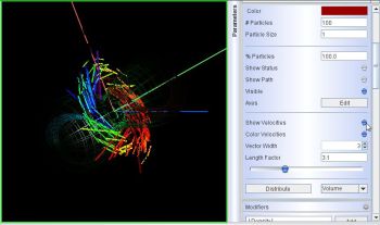
PREVIEW VELOCITY FIELD:
Click on the image on the right to watch a GIF animation that illustrates a practical example of how to visualize the velocity vectors in the 3D Module.
(this video animation has no sound!)
In the example a keplerian velocity field is set up on a disk structure using the Quick mode. It uses a simple preset formula with user defined coefficients for the velocity magnitude as a function of distance from the coordinate center. The velocity vectors show the Doppler effect as color coding. |
 |
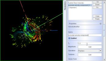
Click on the image on the right to watch a GIF animation that illustrates a practical example of how to use the velocity graph interface of the velocity modifier.
(this video animation has no sound!)
In this example an existing Hubble-type expansion (radial with a linear increase of velocity magnitude) is corrected with a poloidal velocity component that depends on the latitude in a spherical coordinate system.
Download the model of this demo here
(Shape version 2010)! |
 |