Now go back to the modifier list of Blob 2 and click on "Paste". A small dialog window opens (see image on the right). Select "Instance" and confirm with "OK". An "instanced" paste makes sure that any changes to either one of the modifiers is included into the other modifier. Blob 2 appears to have disappeared now. But it is back at the position of Blob 1, because the order of the Translation and Rotation modifier is incorrect (the pasted modifier has been added to the end of the list). With the Translation modifier selected, click on the "Up"-button to the right of the list. Now the Translation will be performed before the rotation and Blob 2 is again opposite to Blob 1. Now change the z-value of the Translation modifier. Not only Blob 2 moves, but both of them change their distance to the origin by the same amount.
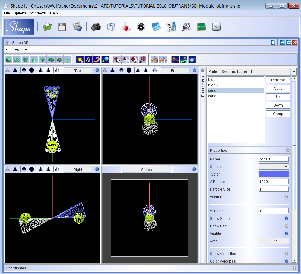
To obtain the cone that goes in opposite direction make a copy of the initial cone using the copy button of the object list. The object copy is automatically selected. To change the direction of the cone, click on the rotate button. Notice that the background of the button turns red to show that it is activated (see top figure on the right). Now go to one of the viewports and drag the mouse with the left button pressed. The object rotates around all three axes simultaneously. You can restrict the rotation to a single axis by pressing the letters x,y or z before and while you drag the mouse to rotate the object.
Open the modifier panel. You will now find a Rotation modifier, which has been created automatically. Click on the modifier to open its properties panel (see the image of the rotation modifier panel on the right). Since we will add two more rotation modifiers label this modifier with the name "invert direction" or something that hints towards the purpose of this modifier. To achieve an inversion of direction, we set either the x or the y rotation to 180. In order to have a point symmetric object, also set the z-rotation to 180.
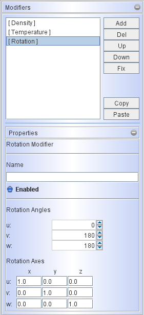
rotation modifier
To rotate the cones away from the main axis add another rotation modifier directly by clicking on the "add" button to the right of the modifier list. Select "Rotation" and click OK to confirm. Name this modifier "off axis". Now change the setting of the u(x)-axis to 10 degrees. The axis of the cone is now inclined with respecto the the axis of the other objects.
Final positioning of the objects after the object transforms have been applied.
IMPORTANT: Note that the result of several sequential rotations depends on the order in which they are performed. When combining several rotation modifiers make sure that they are in the right order. Actually, each individual modifiers already combines three rotations around the x-, y- and z-axis (in that order). If you wish to rotate in the order z-y-x, then you can combine three different rotation modifiers with their rotations set to zero except the axis that you actually want to apply. Also note that the result of combining a rotation and a translation modifier also depends on the order.
To perform the same operation on the other cone, copy this modifier by clicking on the "copy" button to the right of the modifier list. Now select the other cone from the object list at the top of the particle system parameters panel. Go to the modifier list of this cone. Click "paste". A small dialog box appears asking you to choose the paste mode between "Instance" or "Copy". You want our cones to be always aligned to each other. Therefore choose "Instance".
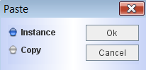
Paste dialog
Now the original and the copied modifier will maintain the same values even if you change only one of them. The "Copy" option makes the copy initially the same, but they are independent for future changes.
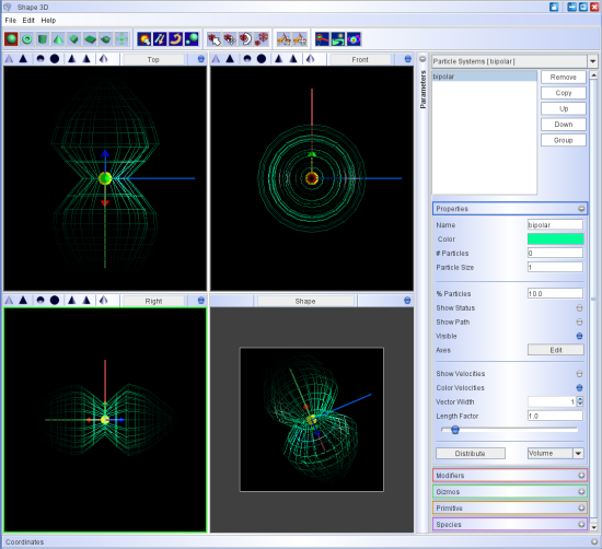
The precession of the two cones around the main axis of the object can now be added my applying another instanced set of Rotation modifiers to both cones. So, repeat the operation of adding a Rotation modifier to one of the cones and the copying it with the "Instance" option to the other cone. If you now change or even animate (see Animation Module) the w(z)-rotation, then the two cones rotate around the main axis of the object.
After animating the z-rotation, the result should be like the animation below (rendered image on the right and the 3D mesh on the left).  |
The sample project file for this tutorial can be downloaded here: sample project. |