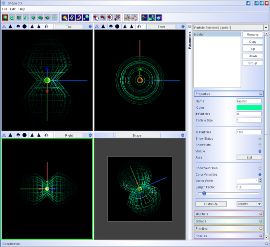
To edit the properties of the emitter select Emitters in the object type drop-down menu at the top of the Object Properties panel.
The emitters with their names appear in a list at the top. Select one to change its properties or remove it (click the Remove button) .
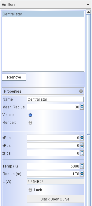
You set size of the emitter icon in the 3D views using the Mesh Radius text field. This size is only relevant for the visualization of the emitter in the viewport. It has no physical meaning.
The Visible button controls whether the emitter is used or not in the model. When you enable the Render button, the emitter will be included in the rendering. Note, however, that it is added on top of the image, i.e. as if the surrounding medium was transparent. This is also for visualization only.
To include the emitter more realistically in the rendering, you can model it as a small spherical dust sphere emitting at the appropriate temperature. Since the size of such a sphere will be near the resolution limit of the 3D volume grid, the accuracy of the emission values will be limited. Make sure that this is adequate for your application.
You can place the emitters anywhere in space by adjusting the position values in cartesian coordinates (xPos, yPos, zPos).
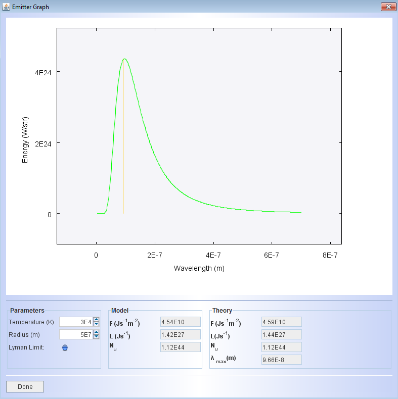
The physical properties of the blackbody model for the emitter can be set in terms of Temperature in Kelvin and the Radius in meters. The bolometric luminosity L in Watts is automatically displayed. When you "lock" the luminosity and then change either the temperature or the radius, the other parameter will be adjusted automatically to maintain the luminosity. The Black Body Curve button opens a graph that shows the spectrum of the emitter within the range of the wavelengths set in the Render Module (see below). It shows additional useful physical quantities.
The emitter graph shows the spectral distribution of the theoretical blackbody. |