banner sun

                                                          Channel Map Module                                                            

  Overview   Lightechoes      
 
       
  Overview >> Video Tutorial
 

Maps or constant radial velocity, i.e. channel maps, are generated and displayed in the Channel Map Module. It also supports the rendering of lightecho maps. The maps are displayed as two-dimensional arrays.

The Channel Map Module is divided in three sections: the toolbar at the top, the parameter panel at the right and the channel map display.

The large blue button label "Map", is similar to the "Shape" render button of the desktop. For the Channel Map Module you have to use this button to render the images instead of the Shape render button.

Map button

Once the parameters for the channel map array have been set up in the parameter panel, you can manually refresh the image array using the array button (calender icon).

array icon

channel map module screenshot

Click on the image to see a higher resolution version.

There are two different options of how to save the channel map images, either altogether in a single grid image or as a sequence. The save button on the left save the grid and the one on the right outputs the image sequence. Make sure to add the extension to the file name. It is used to determine the image file type to be saved, e.g. type image.jpg for a JPEG image or image.gif for a GIF image.

save grid buttonsave sequence button

The next buttons of the toolbar are for the image settings. With the first of them you set the appearance of the image panels, i.e. tickmarks, backgrounds, borders, numbering, etc. The details of the settings are similar to those in the graph settings of the Rendering Module.

image panel settings

The last button of the toolbar sets the image filters, like gaussian blurring (seeing or beam), brightness scaling, contours, etc. The details of the settings are similar to those in the image adjustments of the Rendering Module.

image filter button


Parameter panel

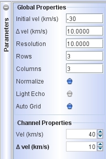
The parameter panel sets the properties of the channel maps sequence.

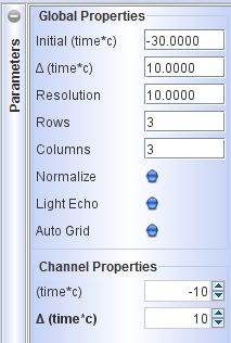
It is devided into two global and individual channel properties. By default the velocity channel map mode is on. If you wish to render lightechoes, then turn on the Lightecho button. Then the panel changes to units appropriate for this mode (see below).

The Initial vel (km/s) parameter is the central velocity of the first channel, which is displayed at the top-left of the display. Δ vel (km/s) is the interval between different channels and Resolution is the total range of velocities that is included in this change, i.e. it includes velocities within the range Δ vel ± Resolution/2. The brightness weighting for this interval is uniform.

The next parameters set how many Rows and Columns the array of channel maps will have. By default the brightness of the maps are normalized to their peak. If you wish to normalize them to the global peak, then disable the Normalize button.

The Auto Grid controls whether the individual channel map parameters are set by the Global Parameters. If this button is disabled, you can select and set individual channel parameters in the Channel Properties section. When you make changes to individual map parameters, then you must use the array button (calender icon) to update the grid. When the Auto Grid is enabled, changing any Global Parameter will automatically update the array. Furthermore, in this case, when you click on the Map button to render, the grid is updated automatically to the Global Properties. Then the intervals between the channels will be uniform.

channel map parameters

The parameter panel of the channel map module.


Lightechoes

Lightechoes are treated in the approximation of short flashes of light propagation through the nebula in on a timescale much larger than the duration of the light source. We have parabolic iso-time surfaces within the nebula with the source at the world coordinate center.

The channels in Shape are set up in terms of the light travel distance, instead of time. That is the distance from the light source to the cell in the grid (or particle) plus the distance to the plane that is perpendicular to the line of sight and goes through the light source.

This "channel distance" is measured in terms of the units used in the 2D Image of the Rendering Module. In this case you have to speficy a distance to produce a sensible result. Note that these can be angular units like arcseconds.

All other parameters and settings are similar in meaning and function as those of the velocity channel map mode.

lightecho parameters

The parameter panel in the lighecho mode.


    16-Jun-2010  
Top