This section is based on the "Tip of the week" published for Shape users on the startup page of the software. |
|
June 14 , 2011 Tip for Mac users Clean your temporary files regularly When opening shape files with very complex objects, on a Macintosh it might happen that loading the file seems to take forever. We found that this can be fixed by cleaning temporary files from your computer. This can be achieved with programs like ¨CleanMyMac¨ or similar. If you find a similar problem or solution for other systems, please share this information with us, so we can pass it on to other users. |
|
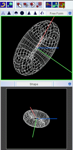
November 25, 2009 Synchronization of Shape and Free Form views Occasionally you might want to play with the orientation of an object without "forgetting" about the original setup in the Shape view of the 3D Module. This can be done using the "Free Form" view. When you first select the Free Form view, it will synchronize to the object orientation of the Shape view. You can then modify your view and, once you are satisfied and want to copy the result to the Shape view, you click on the little blue button in the top-right corner of the Free Form view. Select "Synchronize" to copy the orientation to the Shape view. Note that this move can not be undone, unless you have saved the project and reload it. If you have not done any explicit save, then your previous result might be saved in the autosave file (projectname.autosave.shp).
|
|
November 6, 2009 Interactive Translation and Rotation In the 3D Module occasionally you might have wondered why your object is moving in weird directions when using the interactive translation tool. See the beginning of the animation on the right. Never happened to you? Then here's what to remember when it eventually does. The reason for this is that you have a Rotation modifier below the Translation modifier in the modifier stack. So, whenever you move the object, a rotation is applied after the translation. This mixes things up. The solution is to invert the order of the Rotation and Translation modifiers or manually add an new Translation after the Rotation using the modifier drop-down. The second option allows correct interactive translation without changing the original setup.
|
|
October 20, 2009 Save precious observing time! With Shape you can save tax payer's money and data reduction time for yourself by predicting the observational results of your favorite object before you actually point the telescope at it. It has happened! You might find that your hypothesis can't be tested with the observations that you were about to make. Or you can optimize the pointings to get the best possible results to prove your ideas. Also, consider using Shape to present your hypothesis effectively in your observing proposal, thereby increasing the chances to be granted telescope time and funding.
|
Image: |
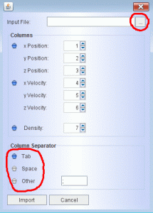
October 15, 2009 Importing external data You can take advantage of Shape's visualization and analysis features for data from external programs, such as hydrodynamical simulations or photoionization models. To do this you can import 3D ascii files with cartesian components of position, velocity and density (or emissivities) given in column format. Just go to the "File" drop-down menu in the 3D Module and choose "Import External System". Then a dialog opens that allows you to select the appropriate columns for the position, velocity and density components. Make sure to select the correct columns separator a the bottom of the dialog. Also, the input file currently should not have a header. In the future we shall include an option to skip a certain number of header lines.
|
|
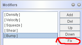
October 5, 2009 Fixed modifiers If you have very complex objects with many segments and several geometry modifiers, then performance might slow down significantly while changing or applying further modifiers , since the whole modifier stack is applied after each change. This can be improved by using the "Fix" button, that is located in the modifier panel. This will apply all modifiers "once and for all". Note that this command should be used with caution, since the modifier stack will disappear and it can not be undone. It is therefore highly recommended to make a backup of the project before applying the Fix command. After fixing the geometry new modifiers can be added and manipulated as usual until you fix them, too.
|
|
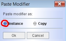
September 21 , 2009 Modifier Instances Often it is necessary to have several sub-objects which share the same modifier, e.g. the velocity field. However, during the modeling process it is inconvenient to separately change the parameters of the shared modifier for each sub-object. Therefore, Shape has the option to copy and paste modifiers as "instances". Instanced modifiers always maintain the same parameters, no matter which of the copies is changed. So, for all the sub-objects only one of the instances has to be changed, while the new values are propagated automatically to the other instances. To make an instanced copy of a modifier use the Copy/Paste buttons for the modifiers and make sure to select "Instance" when you paste the modifier to the other sub-object. The small selection dialog appears in the top-left corner of your screen. If you wish to make a normal copy of the modifier, then choose "Copy". In that case any changes will not be propagated to the original or other copies of the modifier.
From Version 2.5 |
|
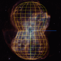
September 7 , 2009 Nebular expansion and the time modifier With Shape you can extrapolate the motion in an object with the Time Modifier. The initial velocity of the particles is then applied to calculate their past or future position (see animated gif image at the top). The velocity is assumed to be constant. To advance time, set up an animation in the Animation Module without any model parameters that change. When you advance the time line, the particles should move. Make sure to disable the Distribute button in the animation parameter panel. This can be used to generate difference images of earlier and later epochs which can be compared with similar images of real objects (see the lower image on the right). To display the difference image, load an observed image in the Main Interface, then right-click on the "observed image" button, which then inverts its colors two show that it is in the difference image mode See the recent paper by Ribeiro et al. (2009) for an application of the time modifier. From Version 2.75 |
|
August 31 , 2009 Visualize and analyze hydrodynamical simulations Shape can be used to visualize numerical hydrodynamical simulations, including velocity data. Just use the File menu of the 3D Module to "Import External System". As long as the data file is in ASCII format and in column format, the data format is flexible. To render the points, in the Shape Helper panel you must set a mesh type, e.g. sphere, even if this is not a sphere. The mesh can be small and should not show in the rendering. See the paper by Steffen, García-Segura & Koning (2009) for an application of this technique. Since Version 2.5 |
|
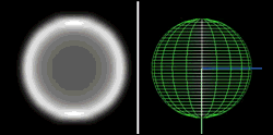
August 19 , 2009 Observed image in 3D Module Not only in the Main Interface can you load an observed image, but since version 3.0 you can also do this in the Shape View of the 3D Interface. To load the image click on the little blue button at the top right of the Shape View panel, then select "Load Observed Image". Using the file dialog that opens, select your image. If possible, make sure that the image is formatted to fit into the view panel (256x256 pixels). If it is larger, then some parts will be clipped. There is a small difference to the Main Interface. In order to mix the 3D view and the observed image to compare them, in the 3D Module you use Ctrl-Right-Mouse-Button and move the mouse from left to right or viceversa. In the Main Interface you do not need to press Ctrl-. Version 3.5 |
|
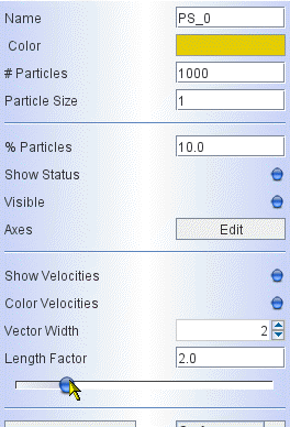
August 15 , 2009 Sliders can be customized Sometimes the default range and precision of a slider, like the one that controls the length of the velocity vectors in the Particle System panel, is inadequate for the parameters of a model. It can be customized to change these settings and its appearance. Right-click on the slider to open the Properties dialog. Then a number of parameters can be changed. See the short animated gif image on the right to see how this works. |
|
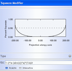
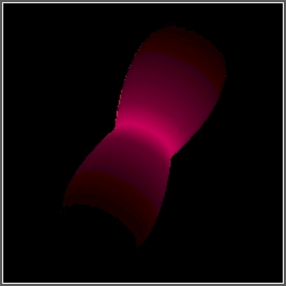
August 7 , 2009 Parameterized Structures - from Tops to Barrels Sometimes it is desirable to describe the shape of an object by an analytical parameterized formula. This can be done in Shape by applying geometry modifiers that use analytical functions to apply to an object. In this example we use a Cone Primitive with equal radii at the ends to make it into a cylinder. Then we apply a Squeeze modifier that uses the analytical graph as shown on the right. The animation at the top was created in the Animation Module by varying the parameter "a" between 0.5 and 8. This produces shapes that range from a "spinning top" for a=0.5, a sphere for a=2 to a more and more cylindrical barrel for a>2. It uses the equation for a "generalized sphere" with an exponent "a" for the coordinates that may differ from 2. A similar idea can be applied to other modifiers or combinations of more than one modifier to produce an infinite variety of structures. A project file for the simple example of the figure on the right can be downloaded here. |
|
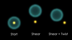
August 2 , 2009 “Twist and Shear” No, this is not the title of a well known song. It’s a rather powerful way to move and rotate your objects in Shape. You might ask, why not use the Rotation and Translation modifiers? The difference is in the behavior of the coordinate system. When you use Rotation and Translation the object’s local coordinate system moves along. Since the velocity field is defined in the local coordinate system, it also moves along. Often, however, you might want to move and rotate an object keeping the origin of the velocity field fixed. Then you can use the Shear and Twist modifiers to translate and rotate the vertices. This is a good alternative to manually moving the vertices with the “Custom Vertex” operators at the top of the 3D Interface. To move or rotate an object by a fixed amount, set a constant value in the Analytic function in the corresponding Graph. Note that, when dealing with rotations, the order in which you place the modifiers is important. Use the “Up” and “Down” buttons in the modifier panel to reorder them. Play with these features and you will soon feel their power. Of course, with the new Animation Module you could use Twist and Shear to make your objects dance to "Twist and shout"... now there´s a challenge! A project file for the simple example of the figure on the right can be downloaded here. |
 |
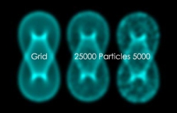
July 28 , 2009 Grid vs. Quick renderer The grid and the physical renderers do not use particle distributions for the renderings. These renderers directly use the meshes and calculate how they intercept the 3D grid in the world space. The images do not have the “noisy” look that is so characteristic of the particle renderings (which might, of course, be just what you need for an object with lots of small clumps). The downside is that the grid renderers are slower and the resolution that you can achieve is currently not as high as that of the quick renderer. Note, however, that particle distributions can be applied to visualize the velocity field in the 3D Module and a variety of quantities in the new plot module. So, make your choice of renderer carefully. If you are in doubt, don´t hesitate to contact your nearest ShapeMaster.
|
 |
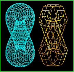
July 21 , 2009 Level of detail in object meshes A primitive object in Shape is constructed
using a mesh of vertices that are connected by
lines or "segments". The precision and level of Version: since 2.5
|
 |
July 15 , 2009 Shortcuts in Shape To increase the speed of the workflow, Shape offers a few keyboard shortcuts. Ctrl-S Render (Shape it!) Rotating and Panning You can limit the action of rotating and panning (right mouse button) to a particular direction (horizontal, vertical, line of sight) by first pressing and maintaining pressed the letters x, y or z. Version: since 2.5
|
|
July 07 , 2009 How to preview a brightness distribution in the 3D module Sometimes it is desirable to have a quick preview of the density distribution on a surface. This can be achieved by taking the following simple steps: 1. Disable the "Show Status" button in the Properties panel of an object in the 3D Module 2. In the "Shape Helper" panel, set the "Type" to "Fill". 3. Make sure you have "Emission" enabled in the "Physical Parameters" Panel 4. To get rid of the glossy look, switch off the "Light" in the "Camera Properties" of the Drop-Down menu at the top-right of the 3D Module. Now you can rotate your object in real-time to preview the surface brightness distribution from different directions as calculated by the "Emission coefficient" in the physical parameters. If you change the dependence on the density "n", the pattern will change in real-time. Note that the rendered result will usually be different, since in the preview the surface is always opaque. Version: 3.1 |
 |
|
|