II. The PUMA Instrument
II.1. DescriptionThe PUMA instrument has been designed and built by a team of astronomers and engeneers of the Instrumentation Department of IAUNAM. It consists basically of a focal reducer, a scanning Fabry Perot, a filter wheel, a calibration system and a CCD detector. All movable parts are remotely controlled from the command room downstairs. The FP can be removed from the optical path allowing direct imaging with interference filters. This systems also permits future development with other optical elements such as grisms or multi-slits.
Basically, PUMA permits:
- Direct imaging of extended objects in various lines: Ha, [NII](6584 A), [SII](6717 A, 6731 A), [OIII](5007 A).
-
- Interferograms of objects in the same lines.
II.1.1. Mechanical design
PUMA has 2 field diaphragms, a calibration lamps wheel, a filter wheel with 8 positions.
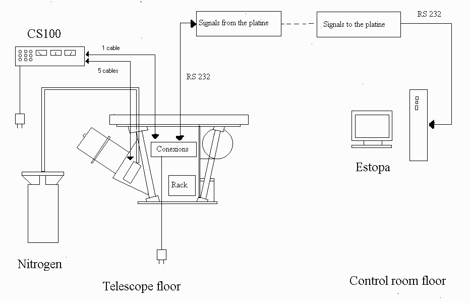
The figure II.1 shows the system design of PUMA. A pictures gallery can be found here.

